A nitrogen compressor boosts pressure of low-pressure nitrogen without
changing gas composition. It converts mechanical energy into gas pressure energy
by reducing gas volume or accelerating flow, supplying high-pressure nitrogen
for cylinder filling, pipeline transmission, pressurized reactions and pressure
retention processes. The operation follows thermodynamic laws. The complete
sequence includes inlet pretreatment, primary compression, inter-stage cooling,
oil and impurity separation, pressure buffering, post-treatment and pressure
relief. Different compressor types differ in internal motion cycles, yet the
overall process logic remains consistent. The core objective is pressure
elevation under controlled temperature rise, acceptable cleanliness and safe
operation. Understanding the sequence, function and interaction of each stage
helps trace root causes of common issues such as pressure drift, overheating and
gas contamination, supporting commissioning, inspection and maintenance.
The process starts with inlet pretreatment. Low-pressure nitrogen from
nitrogen generators, storage tanks or pipelines flows through inlet filters,
pressure regulators and check valves before entering the compression unit.
Although nitrogen is inert, the stream may carry molecular sieve dust, pipeline
rust particles and trace moisture. Inlet filters trap solid particles that would
scratch sealing surfaces, rotors or cylinder walls. Regulators stabilize inlet
pressure and isolate the compression cycle from upstream fluctuations. Check
valves prevent reverse high-pressure flow and back-impact on upstream equipment.
Oil-free models focus mainly on particulate removal; lubricated designs reserve
dedicated downstream oil separation. Pretreatment is the protective front of the
whole workflow. Once filtration fails, contaminants travel downstream and damage
core compression components sequentially.
Primary compression is the pressure-boosting core, divided into positive
displacement and dynamic categories with distinct internal cycles. Reciprocating
piston units convert rotary motion via crank and connecting rod assemblies. One
full cycle includes residual gas expansion, suction, compression and discharge.
As the piston moves downwards, cylinder volume expands, internal pressure drops,
the inlet valve opens and low-pressure nitrogen fills the chamber. On the upward
stroke, the inlet valve closes, trapped gas volume shrinks and pressure and
temperature rise simultaneously. When internal pressure exceeds discharge
backpressure, the outlet valve opens and high-pressure nitrogen flows onward.
Single-stage compression generates substantial heat, so high-pressure
applications adopt multi-stage compression to avoid excessive temperature that
would damage seals and lubricants. Screw compressors use meshing male and female
rotors. Gas fills rotor grooves, which travel from suction to discharge side
with gradually reducing enclosed volume, delivering continuous compression and
smoother outlet flow without cyclic pulsation. Centrifugal compressors are
dynamic machines. High-speed impellers transfer kinetic energy to nitrogen, and
diffusers reduce flow velocity to convert kinetic energy into pressure energy,
suited for large-flow, medium and low-pressure continuous supply.
Inter-stage cooling is mandatory for multi-stage arrangements. Compression
raises gas internal energy and temperature. Hot gas entering the next
compression stage reduces efficiency and accelerates degradation of seals and
lubricants; polymer seals in oil-free variants may deform under excessive heat.
After each compression stage, nitrogen passes into intercoolers cooled by water
or air, bringing gas temperature close to initial suction conditions. Water
vapour condenses inside coolers and automatic drains remove condensate to
prevent liquid carry-over into subsequent compression chambers. Cooling
performance directly governs downstream load. Fouled heat exchange surfaces,
insufficient airflow or low cooling water flow leave outlet temperature
elevated, raising overall energy consumption and weakening long-term
reliability.
Oil separation is unique to lubricated compressors. Lubricant mixes with
nitrogen during compression and forms oil mist carried by high-speed gas.
Multi-stage separator cartridges remove oil droplets through gravity settling,
inertial impaction and adsorption. Collected lubricant drains back to the
crankcase for recirculation. Coarse separation captures large droplets while
fine filters remove submicron mist to meet residual oil limits. Failed
separation leads to excessive oil carry-over, contaminating storage, piping and
downstream processes. For systems paired with carbon molecular sieve nitrogen
generators, oil-laden return gas can permanently deactivate adsorbent media.
Oil-free compressors eliminate oil separation but rely on specialized rotor
coatings and seals to avoid contact between lubricant and process gas.
Pressure buffering follows the compression discharge. Compressors generate
pressure pulsation, especially reciprocating types. Receiver tanks smooth
pulsation and deliver steady nitrogen flow. Pressure transmitters and gauges
feed signals to the control system for load and unload regulation. When tank
pressure reaches the upper setpoint, the machine unloads and suspends effective
compression; when pressure falls to the lower threshold, loading resumes to
maintain stable delivery. Buffers decouple the compression cycle from variable
downstream demand and avoid frequent compressor cycling caused by sudden
consumption changes. Safety relief valves serve as passive protection, opening
to vent gas if pressure control fails and overpressure occurs.
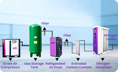
Optional post-treatment includes dryers and fine filters according to
process requirements. Cooled compressed nitrogen contains saturated water
vapour. Dryers reduce dew point for moisture-sensitive applications, while
polishing filters capture residual dust and mist escaped from upstream stages.
Post-treatment is normally installed after the receiver and close to consumption
points to prevent recontamination during pipeline transport. Filling manifolds
and control valves are added for cylinder filling workflows.
Interlock and control logic runs across the whole process. Sensors monitor
inlet pressure, inter-stage discharge temperature, outlet pressure, differential
pressure and oil level. The controller manages auto start-stop, load cycling and
cooling circuit actuation. Alarms trigger for over-temperature, overpressure,
low oil level or high filter differential pressure, and protective shutdown
activates under severe conditions to stop compression and prevent cascading
failure. Interlocks form the safety boundary and avoid seal rupture or gas
release under out-of-limits operation.
The whole compression workflow forms an interconnected closed chain. Inlet
contaminants abrade the main unit; high compression heat burdens cooling
hardware; poor cooling impairs oil separation; separation failure contaminates
downstream piping; insufficient buffer volume triggers frequent pressure swings.
System matching must align compressor process parameters with upstream nitrogen
generation and downstream usage, including inlet pressure, flow, residual oil
and dew point specifications. Maintenance inspections follow gas flow direction,
with periodic sensor calibration, heat exchanger cleaning and consumable
replacement to keep each section within design conditions. Only coordinated
stable operation of the full process chain enables the nitrogen compressor to
deliver consistent pressure and gas quality reliably for downstream
processes.